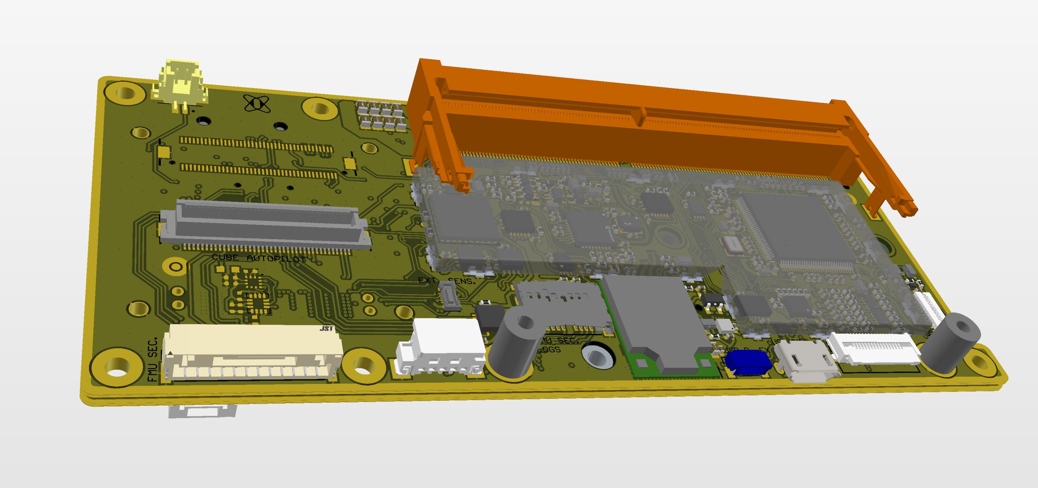
# DCS2.Pilot

<details>

<summary><strong>Release notes</strong></summary>

#### **rev.2**

* Added side platting for the board
* Board dimension expanded 1mm in width and 1mm in height
* Added TPM module
* Added additional RTC circuit + rail for possibility to charge battery externally
* Added EMI shield on the TOP side of the board.
* Cube SPI + SRLX signals routed to board-to-board connector
* Onboard FMU signals (4xPWM, 1xUART) routed to board-to-board connector in parallel
* Jetson configuration USB routed to board-to-board connector
* 1V8\_Adapter rail removed from board-to-board connector
* Jetson standoffs mechanically reinforced
* Changed MPN for SSD oscillator
* Changed MPN for CAN transceivers
* Added jumpers for CAN1/2 of Cube red connection

#### **rev.1.1a**

* Cube (RED version) - series capacitors removed on ETH signals
* Jetson EEPROM type changed \\

#### **rev.1.1**

* Interrupt signal for onboard FMU external IMU reconnected to PD1
* Onboard FMU - alarm output routed to PB15 (Buzzer was not available in previous revisions)
* Onboard FMU - PA0 used as VCC sensing (VCC sensing not available in prev. revisions)
* HDMI connector replaced to ZIF type.
* Jetson power logic - added support for supply voltage range of 5V-20V

#### **rev.1**

* PPM input routed to PA6 / TIM3\_CH1 (PPM was not available in prev. Revisions for Onboard FMU)
* Added TVS protection for ethernet ports
* Thermal design of mechanically stressed connector PADs replaced with direct connection
* Added redundant IMU and magnetometer for onboard FMU (assembly variant)
* Solder mask color changed to green\\

#### **rev.0.1 (preproduction series)**

* Onboard FMU based on STM32H743
* RMII routed to onboard FMU
* USB to Cube multiplexed and routed also to onboard FMU
* Added SD-card connector (onboard FMU logs)
* Rework of CSI (group length matching of connectable ports)
* Repaired HDMI DDC bus (HDMI was not working properly)
* JST connector for onboard FMU replaced with 12-pin type
* PPM routed also to adapter board

</details>

<figure><img src="https://341257526-files.gitbook.io/~/files/v0/b/gitbook-x-prod.appspot.com/o/spaces%2FkuuT7PXOBpck5wDlb6XM%2Fuploads%2Fgit-blob-d050855d178cbb16012c7516ee1c93e173d3e756%2FDCS2.Pilot_overview.svg?alt=media" alt=""><figcaption><p>DCS2.Pilot v2.0</p></figcaption></figure>

## Description

*Board description*

***

## Dimensions

<figure><img src="/files/aGL5yhJluts5qGPpfCGF" alt=""><figcaption></figcaption></figure>

***

## Power supply

<figure><img src="/files/NyWz7zafGOTFYxK6Xu2N" alt=""><figcaption></figcaption></figure>

### Power consumption

*Podobne ako v DCS1*

***

## Peripherals

{% hint style="info" %}
Some of the peripherals are prepared for future use (dotted lines). 100Mbit Eth line, Serial 8 and CAN3 are related to different assembly variants of the board and usage of different Cube autopilot versions (Cube Red)
{% endhint %}

<figure><img src="/files/mZnTEwNMuBRYuEy7G6tV" alt=""><figcaption></figcaption></figure>

***

## Connectors and pinouts

### Top side onboard connectors <a href="#top-side-onboard-connectors" id="top-side-onboard-connectors"></a>

<figure><img src="/files/wNHGqtGaOrpIuEvRnQPH" alt=""><figcaption></figcaption></figure>

<details>

<summary><strong>PPM</strong></summary>

Matching connector JST GHR-03V-S

{% hint style="info" %}
5V supply limited to 1A by internal current limiter
{% endhint %}

{% hint style="info" %}
Position remains the same as in version v1.x, only pin 1 marking was fixed in v2.0
{% endhint %}

| pin | function        |
| --- | --------------- |
| 1   | PPM\_SBUS\_PROT |
| 2   | 5V\_CRUCIAL     |
| 3   | GND             |

</details>

<details>

<summary><strong>CONTROL</strong></summary>

1.8V logic

<table><thead><tr><th width="372.45045045045043">pin</th><th>function</th></tr></thead><tbody><tr><td>1</td><td>SYS_RST</td></tr><tr><td>2</td><td>GND</td></tr><tr><td>3</td><td>FC_REC (Force recovery)</td></tr><tr><td>4</td><td>GND</td></tr><tr><td>5</td><td>PWR_BTN</td></tr><tr><td>6</td><td>GND</td></tr></tbody></table>

</details>

<details>

<summary><strong>NVME</strong></summary>

* M2 key M standard connector
* Connector includes PCIE x4 and I2C bus
* Ready to mount NVME SSD in M2 2242 size

</details>

<details>

<summary><strong>B2B POWER CONNECTOR (PDB/Power board)</strong></summary>

<table><thead><tr><th width="370.45045045045043">pin</th><th>function</th></tr></thead><tbody><tr><td>1</td><td>5V_PERIPH</td></tr><tr><td>2</td><td>5V_CRUCIAL</td></tr><tr><td>3</td><td>3V3_SOM</td></tr><tr><td>4</td><td>VDD_JETSON (v2.0) / 18V_SOM (v1.x)</td></tr><tr><td>5</td><td>N.C. (v2.0) / ?V_PAYLOAD (v1.x)</td></tr><tr><td>6</td><td>5V_SAFETY</td></tr><tr><td>7</td><td>GND</td></tr><tr><td>8</td><td>GND</td></tr></tbody></table>

</details>

<details>

<summary><strong>B2B SIGNAL CONNECTOR (PDB/Power board)</strong></summary>

<table><thead><tr><th width="278.45045045045043">pin</th><th>function</th></tr></thead><tbody><tr><td>1</td><td>CAN1_N</td></tr><tr><td>2</td><td>CAN1_P</td></tr><tr><td>3</td><td>GND</td></tr><tr><td>4</td><td>CAN2_N</td></tr><tr><td>5</td><td>CAN2_P</td></tr><tr><td>6</td><td>JETSON_ID (v2.0) / GND (v1.x)</td></tr><tr><td>7</td><td>I2C_SCL</td></tr><tr><td>8</td><td>I2C_SDA</td></tr><tr><td>9</td><td>SERIAL 1 TX (v2.0) / RESERVED (v1.x)</td></tr><tr><td>10</td><td>SERIAL 1 RX (v2.0) / RESERVED (v1.x)</td></tr><tr><td>11</td><td>GPIO/PWM OUT 4 (v2.0) / RESERVED (v1.x)</td></tr><tr><td>12</td><td>GPIO/PWM OUT 3 (v2.0) / RESERVED (v1.x)</td></tr><tr><td>13</td><td>GPIO/PWM OUT 2 (v2.0) / RESERVED (v1.x)</td></tr><tr><td>14</td><td>GPIO/PWM OUT 1 (v2.0) / RESERVED (v1.x)</td></tr><tr><td>15</td><td>RESERVED</td></tr><tr><td>16</td><td>BAT_V_SENSE</td></tr><tr><td>17</td><td>BAT_I_SENSE</td></tr><tr><td>18</td><td>RTC_BATTERY (v2.0) / RESERVED (v1.x)</td></tr><tr><td>19</td><td>MOD_SLEEP</td></tr><tr><td>20</td><td>SYS_RST_HS</td></tr></tbody></table>

</details>

<details>

<summary><strong>B2B ADAPTER CONNECTORS</strong></summary>

Pinouts and reference design will be provided as example Altium Designer project.

</details>

***

### Bottom side onboard connectors

<figure><img src="/files/zPgRhKjhSkU4fLL8sRLC" alt=""><figcaption></figcaption></figure>

<details>

<summary><strong>BEEP</strong></summary>

Matching connector Hirose DF13-2S-1.25C

| pin | function |
| --- | -------- |
| 1   | BUZZER+  |
| 2   | BUZZER-  |

</details>

<details>

<summary><strong>FAN</strong></summary>

* Matching with Molex 51021-0400 cable header
* Ccompatible with Orin NX original cooler

{% hint style="info" %}
5V supply limited to 200mA by internal current limiter
{% endhint %}

| pin | function   |
| --- | ---------- |
| 1   | GND        |
| 2   | 5V\_PERIPH |
| 3   | FAN\_TACH  |
| 4   | FAN\_PWM   |

</details>

<details>

<summary><strong>ETH_EXP</strong></summary>

* 505110-1692 connector type
* possible to use aepilot1\_ethernet\_expansion\_board, to expand to RJ45

{% hint style="info" %}
5V supply limited to 1A by internal current limiter
{% endhint %}

<table><thead><tr><th width="367">pin</th><th>function</th></tr></thead><tbody><tr><td>1</td><td>GBE_B3_P</td></tr><tr><td>2</td><td>GBE_B3_N</td></tr><tr><td>3</td><td>GND</td></tr><tr><td>4</td><td>GBE_M2_P</td></tr><tr><td>5</td><td>GBE_M2_N</td></tr><tr><td>6</td><td>GND</td></tr><tr><td>7</td><td>GBE_M1_P</td></tr><tr><td>8</td><td>GBE_M1_N</td></tr><tr><td>9</td><td>GND</td></tr><tr><td>10</td><td>GBE_M0_P</td></tr><tr><td>11</td><td>GBE_M0_N</td></tr><tr><td>12</td><td>GND</td></tr><tr><td>13</td><td>GBE_LED_LINK</td></tr><tr><td>14</td><td>GBE_LED_ACT</td></tr><tr><td>15</td><td>5V_PERIPH</td></tr><tr><td>16</td><td>5V_PERIPH</td></tr></tbody></table>

</details>

<details>

<summary><strong>FMU SEC.</strong></summary>

Matching connector JST GHR-12V-S

{% hint style="info" %}
5V supply limited to 1A by internal current limiter
{% endhint %}

{% hint style="info" %}
Connector related to onboard FMU
{% endhint %}

{% hint style="info" %}
Position remains the same as in version v1.x, only pin 1 marking was fixed in v2.0
{% endhint %}

| pin | function       |
| --- | -------------- |
| 1   | 5V\_SAFETY     |
| 2   | 5V\_SAFETY     |
| 3   | SERIAL 2 TX    |
| 4   | SERIAL 2 RX    |
| 5   | SERIAL 1 TX    |
| 6   | SERIAL 1 RX    |
| 7   | GPIO/PWM OUT 1 |
| 8   | GPIO/PWM OUT 2 |
| 9   | GPIO/PWM OUT 3 |
| 10  | GPIO/PWM OUT 4 |
| 11  | GND            |
| 12  | GND            |

</details>

<details>

<summary><strong>USB_DEV</strong></summary>

* USB type micro B connector
* Possible to use only as Jetson USB-device
* When a micro USB cable is connected between the board and the host PC, Jetson acts like a USB device.

</details>

<details>

<summary><strong>USB D. EX</strong></summary>

* JST SM04B-SURS-TF(LF)(SN) connector type
* Possibility to route USB\_DEV signals to drone case

{% hint style="warning" %}
If expansion cables are long, be aware of using a suitable cable with proper shielding
{% endhint %}

| pin | function |
| --- | -------- |
| 1   | GND      |
| 2   | D\_P     |
| 3   | D\_N     |
| 4   | VBUS     |

</details>

<details>

<summary><strong>HDMI_OUT</strong></summary>

503566-2102 connector type

{% hint style="info" %}
5V supply limited to 0.2A by internal current limiter
{% endhint %}

| pin | function        |
| --- | --------------- |
| 1   | GND             |
| 2   | HDMI\_DATA2\_P  |
| 3   | NC              |
| 4   | HDMI\_DATA2\_N  |
| 5   | GND             |
| 6   | GND             |
| 7   | HDMI\_DATA1\_N  |
| 8   | HDMI\_DATA0\_P  |
| 9   | HDMI\_DATA1\_P  |
| 10  | HDMI\_DATA0\_N  |
| 11  | GND             |
| 12  | GND             |
| 13  | HDMI\_CLK\_N    |
| 14  | HDMI\_CEC       |
| 15  | HDMI\_CLK\_P    |
| 16  | HDMI\_DDC\_CLK  |
| 17  | NC              |
| 18  | GND             |
| 19  | HDMI\_DDC\_DATA |
| 20  | HDMI\_DETECT    |
| 21  | 5V              |

</details>

<details>

<summary><strong>Wi-Fi module</strong></summary>

The onboard Wi-Fi/Bluetooth module contains two MHF4 micro-coax pigtail connectors for antennas. Suitable cable + antenna combination:

* Connector + cable: C213GST-025MC137B-MHF4L
* Antenna: 2JW1102--C943B

{% hint style="danger" %}
Do not run the Wi-Fi module without antennas connected!
{% endhint %}

</details>


---

# Agent Instructions: Querying This Documentation

If you need additional information that is not directly available in this page, you can query the documentation dynamically by asking a question.

Perform an HTTP GET request on the current page URL with the `ask` query parameter:

```
GET https://test-airvolute.gitbook.io/test-airvolute-docs/autopilots/dronecore-2/boards/pilot-boards/dcs2.pilot.md?ask=<question>
```

The question should be specific, self-contained, and written in natural language.
The response will contain a direct answer to the question and relevant excerpts and sources from the documentation.

Use this mechanism when the answer is not explicitly present in the current page, you need clarification or additional context, or you want to retrieve related documentation sections.
