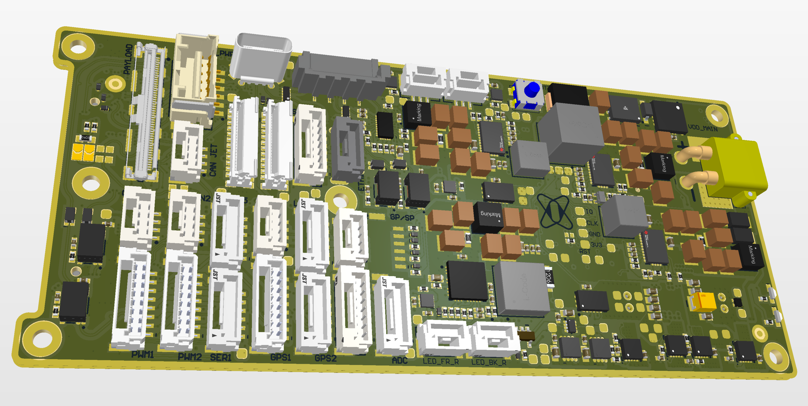
# Default expansion board

<figure><img src="https://341257526-files.gitbook.io/~/files/v0/b/gitbook-x-prod.appspot.com/o/spaces%2FkuuT7PXOBpck5wDlb6XM%2Fuploads%2Fgit-blob-68f2d53ae4e0caf872090a41352198502f64165a%2FDCS2.Default_expansion_overview.svg?alt=media" alt=""><figcaption><p>DCS2.Default_expansion v1.0</p></figcaption></figure>

## Description <a href="#description" id="description"></a>

*Board description*

***

## Dimensions <a href="#dimensions" id="dimensions"></a>

<figure><img src="/files/7bnmCfOn7lyY8zuprskO" alt=""><figcaption></figcaption></figure>

***

## Power supply <a href="#power-supply" id="power-supply"></a>

<figure><img src="/files/EcYqOhoJjukmHdbpkFGd" alt=""><figcaption></figcaption></figure>

### Power consumption <a href="#power-consumption" id="power-consumption"></a>

*Podobne ako v DCS1*

***

## Peripherals <a href="#peripherals" id="peripherals"></a>

<figure><img src="/files/Mvj2qPBwK7MmdiDZIk72" alt=""><figcaption></figcaption></figure>

***

<h2 align="center">Connectors and pinouts</h2>

### Top side connectors

<figure><img src="/files/6NszYoQjHksIJYQCj4bN" alt=""><figcaption></figcaption></figure>

<details>

<summary><strong>VDD_MAIN</strong></summary>

* Matching connector XT30
* Voltage range 20-55VDC

</details>

<details>

<summary><strong>PAYLOAD SIGNALS</strong></summary>

Matching connector Hirose DF36-50P-0.4SD

<table><thead><tr><th width="245">pin</th><th>function</th></tr></thead><tbody><tr><td>1</td><td>GbE_DA_N</td></tr><tr><td>2</td><td>GbE_DA_P</td></tr><tr><td>3</td><td>GbE_DB_N</td></tr><tr><td>4</td><td>GbE_DB_P</td></tr><tr><td>5</td><td>GbE_DC_N</td></tr><tr><td>6</td><td>GbE_DC_P</td></tr><tr><td>7</td><td>GbE_DD_N</td></tr><tr><td>8</td><td>GbE_DD_P</td></tr><tr><td>9</td><td>CAM3_I2C_SDA</td></tr><tr><td>10</td><td>CAM3_I2C_SCL</td></tr><tr><td>11</td><td>CAM3_MCLK</td></tr><tr><td>12</td><td>CAM3_PWDN</td></tr><tr><td>13</td><td>CAM3_CLK_P</td></tr><tr><td>14</td><td>CAM3_CLK_N</td></tr><tr><td>15</td><td>CAM3_D1_P</td></tr><tr><td>16</td><td>CAM3_D1_N</td></tr><tr><td>17</td><td>CAM3_D0_P</td></tr><tr><td>18</td><td>CAM3_D0_N</td></tr><tr><td>19</td><td>CAM2_I2C_SDA</td></tr><tr><td>20</td><td>CAM2_I2C_SCL</td></tr><tr><td>21</td><td>CAM2_MCLK</td></tr><tr><td>22</td><td>CAM2_PWDN</td></tr><tr><td>23</td><td>CAM2_CLK_P</td></tr><tr><td>24</td><td>CAM2_CLK_N</td></tr><tr><td>25</td><td>CAM2_D1_P</td></tr><tr><td>26</td><td>CAM2_D1_N</td></tr><tr><td>27</td><td>CAM2_D0_P</td></tr><tr><td>28</td><td>CAM2_D0_N</td></tr><tr><td>29</td><td>USB1_PWRCTL</td></tr><tr><td>30</td><td>USB1_OC</td></tr><tr><td>31</td><td>USB1_D_P</td></tr><tr><td>32</td><td>USB1_D_N</td></tr><tr><td>33</td><td>USB1_SSTX_P</td></tr><tr><td>34</td><td>USB1_SSTX_N</td></tr><tr><td>35</td><td>USB1_SSRX_P</td></tr><tr><td>36</td><td>USB1_SSRX_N</td></tr><tr><td>37</td><td>USB0_SSTX_P</td></tr><tr><td>38</td><td>USB0_SSTX_N</td></tr><tr><td>39</td><td>USB0_SSRX_P</td></tr><tr><td>40</td><td>USB0_SSRX_N</td></tr><tr><td>41</td><td>CAN1_H (available through solder bridges)</td></tr><tr><td>42</td><td>CAN1_L (available through solder bridges)</td></tr><tr><td>43</td><td>CAN2_H (available through solder bridges)</td></tr><tr><td>44</td><td>CAN2_L (available through solder bridges)</td></tr><tr><td>45</td><td>UART_JET_TX</td></tr><tr><td>46</td><td>UART_JET_RX</td></tr><tr><td>47</td><td>JETSON_GPIOx</td></tr><tr><td>48</td><td>JETSON_GPIOx</td></tr><tr><td>49</td><td>SERIAL1_TX (available through solder bridges)</td></tr><tr><td>50</td><td>SERIAL1_RX (available through solder bridges)</td></tr></tbody></table>

</details>

<details>

<summary><strong>PAYLOAD POWER</strong></summary>

Matching connector Molex 502578-060x

{% hint style="info" %}
VDD\_BATT rail is fused with 1A fuse
{% endhint %}

{% hint style="info" %}
5V rail is internally limited to 2A
{% endhint %}

| pin | function   |
| --- | ---------- |
| 1   | VDD\_BATT  |
| 2   | N.C.       |
| 3   | 5V\_PERIPH |
| 4   | GND        |
| 5   | GND        |
| 6   | GND        |

</details>

<details>

<summary><strong>I2C2</strong></summary>

Matching connector JST GHR-04V-S

{% hint style="info" %}
I2C2, CAN1, CAN2, ADC connectors share the same power rail internally limited to 1A
{% endhint %}

| pin | function    |
| --- | ----------- |
| 1   | 5V\_CRUCIAL |
| 2   | I2C2\_SCL   |
| 3   | I2C2\_SDA   |
| 4   | GND         |

</details>

<details>

<summary><strong>CAN1</strong></summary>

Matching connector JST GHR-04V-S

{% hint style="info" %}
I2C2, CAN1, CAN2, ADC connectors share the same power rail internally limited to 1A
{% endhint %}

| pin | function    |
| --- | ----------- |
| 1   | 5V\_CRUCIAL |
| 2   | CAN1\_H     |
| 3   | CAN1\_L     |
| 4   | GND         |

</details>

<details>

<summary><strong>CAN2</strong></summary>

Matching connector JST GHR-04V-S

{% hint style="info" %}
I2C2, CAN1, CAN2, ADC connectors share the same power rail internally limited to 1A
{% endhint %}

| pin | function    |
| --- | ----------- |
| 1   | 5V\_CRUCIAL |
| 2   | CAN2\_H     |
| 3   | CAN2\_L     |
| 4   | GND         |

</details>

<details>

<summary><strong>ADC</strong></summary>

Matching connector JST GHR-06V-S

{% hint style="info" %}
I2C2, CAN1, CAN2, ADC connectors share the same power rail internally limited to 1A
{% endhint %}

| pin | function    |
| --- | ----------- |
| 1   | 5V\_CRUCIAL |
| 2   | 5V\_CRUCIAL |
| 3   | BAT\_ISENSE |
| 4   | BAT\_VSENSE |
| 5   | GND         |
| 6   | GND         |

</details>

<details>

<summary><strong>SERIAL5</strong></summary>

Matching connector JST GHR-06V-S

{% hint style="info" %}
SERIAL5, GPS1, GPS2, SPI shares the same power rail internally limited to 2A
{% endhint %}

| pin | function    |
| --- | ----------- |
| 1   | 5V\_CRUCIAL |
| 2   | SERIAL5\_TX |
| 3   | SERIAL5\_RX |
| 4   | S.BUS\_OUT  |
| 5   | NC          |
| 6   | GND         |

</details>

<details>

<summary><strong>GPS1</strong></summary>

Matching connector JST GHR-08V-S

{% hint style="info" %}
SERIAL5, GPS1, GPS2, SPI shares the same power rail internally limited to 2A
{% endhint %}

| pin | function             |
| --- | -------------------- |
| 1   | 5V\_CRUCIAL          |
| 2   | SERIAL3\_TX          |
| 3   | SERIAL3\_RX          |
| 4   | I2C1\_SCL            |
| 5   | I2C1\_SDA            |
| 6   | SAFETY               |
| 7   | IO-LED\_SAFETY\_PROT |
| 8   | GND                  |

</details>

<details>

<summary><strong>GPS2</strong></summary>

Matching connector JST GHR-06V-S

{% hint style="info" %}
SERIAL5, GPS1, GPS2, SPI shares the same power rail internally limited to 2A
{% endhint %}

| pin | function    |
| --- | ----------- |
| 1   | 5V\_CRUCIAL |
| 2   | SERIAL4\_TX |
| 3   | SERIAL4\_RX |
| 4   | I2C2\_SCL   |
| 5   | I2C2\_SDA   |
| 6   | GND         |

</details>

<details>

<summary><strong>SPI (FMU)</strong></summary>

Matching connector JST GHR-07V-S

{% hint style="info" %}
SERIAL5, GPS1, GPS2, SPI shares the same power rail internally limited to 2A
{% endhint %}

| pin | function    |
| --- | ----------- |
| 1   | 5V\_CRUCIAL |
| 2   | SPI\_SCK    |
| 3   | SPI\_MISO   |
| 4   | SPI\_MOSI   |
| 5   | SPI\_CS0    |
| 6   | SPI\_CS1    |
| 7   | GND         |

</details>

<details>

<summary><strong>SERIAL1</strong></summary>

Matching connector JST GHR-06V-S

{% hint style="info" %}
5V power rail internally limited to 1A
{% endhint %}

| pin | function     |
| --- | ------------ |
| 1   | 5V\_PERIPH   |
| 2   | SERIAL1\_TX  |
| 3   | SERIAL1\_RX  |
| 4   | SERIAL1\_CTS |
| 5   | SERIAL1\_RTS |
| 6   | GND          |

</details>

<details>

<summary><strong>LIDAR</strong></summary>

Matching connector JST GHR-06V-S

{% hint style="info" %}
5V power rail internally limited to 0.5A
{% endhint %}

{% hint style="info" %}
Pinout to match original Lightware lidars in its I2C communication mode, using a straight cable
{% endhint %}

| pin | function    |
| --- | ----------- |
| 1   | NC          |
| 2   | I2C2\_SDA   |
| 3   | I2C2\_SCL   |
| 4   | I2C2\_SDA   |
| 5   | GND         |
| 6   | 5V\_CRUCIAL |

</details>

<details>

<summary><strong>PWM1</strong></summary>

Matching connector JST GHR-08V-S

| pin | function                              |
| --- | ------------------------------------- |
| 1   | IO-CH1-PROT ( "PX" -> SPI\_FMU\_MISO) |
| 2   | IO-CH2-PROT ( "PX" -> SPI\_FMU\_MOSI) |
| 3   | IO-CH3-PROT ( "PX" -> SPI\_FMU\_SCK)  |
| 4   | IO-CH4-PROT ( "PX" -> SPI\_FMU\_CS1)  |
| 5   | IO-CH5-PROT ( "PX" -> SPI\_FMU\_CS2)  |
| 6   | IO-CH6-PROT                           |
| 7   | IO-CH7-PROT ( "PX" -> FMU\_CH8 )      |
| 8   | GND                                   |

</details>

<details>

<summary><strong>PWM2</strong></summary>

Matching connector JST GHR-08V-S

| pin | function                         |
| --- | -------------------------------- |
| 1   | IO-CH8-PROT ( "PX" -> FMU\_CH8 ) |
| 2   | FMU\_CH1                         |
| 3   | FMU\_CH2                         |
| 4   | FMU\_CH3                         |
| 5   | FMU\_CH4                         |
| 6   | FMU\_CH5                         |
| 7   | FMU\_CH6                         |
| 8   | GND                              |

</details>

<details>

<summary><strong>SPI_JET</strong></summary>

* Matching connector JST GHR-07V-S
* 3V3 SPI voltage logic

{% hint style="info" %}
SPI\_JET and CAN\_JET share the same power supply rail, internally limited to 0.5A
{% endhint %}

| pin | function        |
| --- | --------------- |
| 1   | 5V\_JET\_PERIPH |
| 2   | SPI0\_CLK       |
| 3   | SPI0\_MISO      |
| 4   | SPI0\_MOSI      |
| 5   | SPI0\_CS0       |
| 6   | SPI0\_CS1       |
| 7   | GND             |

</details>

<details>

<summary><strong>CAN_JET</strong></summary>

Matching connector JST GHR-04V-S

{% hint style="info" %}
SPI\_JET and CAN\_JET share the same power supply rail, internally limited to 0.5A
{% endhint %}

| pin | function        |
| --- | --------------- |
| 1   | 5V\_JET\_PERIPH |
| 2   | CAN\_H          |
| 3   | CAN\_L          |
| 4   | GND             |

</details>

<details>

<summary><strong>ETH1</strong></summary>

Matching connector JST GHR-05V-S

| pin | function   |
| --- | ---------- |
| 1   | ETH\_RX\_N |
| 2   | ETH\_RX\_P |
| 3   | GND        |
| 4   | ETH\_TX\_N |
| 5   | ETH\_TX\_P |

</details>

<details>

<summary><strong>USB2</strong></summary>

Matching connector JST GHR-04V-S

{% hint style="info" %}
5V power rail internally limited to 2A
{% endhint %}

| pin | function   |
| --- | ---------- |
| 1   | 5V\_PERIPH |
| 2   | USB\_D\_N  |
| 3   | USB\_D\_P  |
| 4   | GND        |

</details>

<details>

<summary><strong>PCIE EXT</strong></summary>

* FH41-20S-0.5SH connector type
* PCIE x1 bus
* Possibility to use an expansion board to the M2\_keyM connector, and use another external NVME.

{% hint style="info" %}
3V3 power rail internally limited to 2A
{% endhint %}

| pin | function      |
| --- | ------------- |
| 1   | GND           |
| 2   | TX\_P         |
| 3   | TX\_N         |
| 4   | GND           |
| 5   | RX\_P         |
| 6   | RX\_N         |
| 7   | GND           |
| 8   | CLK\_P        |
| 9   | CLK\_N        |
| 10  | GND           |
| 11  | SUSCLK 32KHZ  |
| 12  | GND           |
| 13  | #PCIE\_RST    |
| 14  | #PCIE\_CLKREQ |
| 15  | #PCIE\_WAKE   |
| 16  | 3V3\_AD       |
| 17  | 3V3\_AD       |
| 18  | 3V3\_AD       |
| 19  | 3V3\_AD       |
| 20  | 3V3\_AD       |

</details>

<details>

<summary><strong>CSI0, CAM1 (2-lanes CSI)</strong></summary>

* 501951-2210 connector type
* 2 lanes MIPI CSI connectors
* I2C and PWDN are 3V3 logic

{% hint style="info" %}
CAM0, CAM1 share the same power rail, internally limited to 0.5A
{% endhint %}

{% hint style="info" %}
JET\_CAM\_SUPPLY is configurable to 3V3 or 5V by solder bridge on the bottom side of the board

SB open = 3V3 , SB closed = 5V
{% endhint %}

<figure><img src="/files/cnKuK9expGzcYjba0dxU" alt=""><figcaption><p>Location of CAM_SUPPLY solder bridge</p></figcaption></figure>

{% hint style="danger" %}
Pay attention to the cable pins' orientation (same/opposite side contacts). Cameras from different manufacturers can have different pin orders, so a wrong cable can cause a short-circuit!
{% endhint %}

| pin | function    |
| --- | ----------- |
| 1   | CAM\_SUPPLY |
| 2   | I2C\_SDA    |
| 3   | I2C\_SCL    |
| 4   | GND         |
| 5   | MCLK        |
| 6   | PWDN        |
| 7   | GND         |
| 8   | NC          |
| 9   | NC          |
| 10  | GND         |
| 11  | NC          |
| 12  | NC          |
| 13  | GND         |
| 14  | CSI\_CLK\_P |
| 15  | CSI\_CLK\_N |
| 16  | GND         |
| 17  | CSI\_D1\_P  |
| 18  | CSI\_D1\_N  |
| 19  | GND         |
| 20  | CSI\_D0\_P  |
| 21  | CSI\_D0\_N  |
| 22  | GND         |

</details>

<details>

<summary><strong>LED_FR_L</strong></summary>

Matching connector JST GHR-03V-S

{% hint style="info" %}
LED\_FR\_L, LED\_FR\_R connectors share the same power rail internally limited to 2A
{% endhint %}

| pin | function   |
| --- | ---------- |
| 1   | GND        |
| 2   | LED\_FL    |
| 3   | 5V\_PERIPH |

</details>

<details>

<summary><strong>LED_FR_R</strong></summary>

Matching connector JST GHR-03V-S

{% hint style="info" %}
LED\_FR\_L, LED\_FR\_R connectors share the same power rail internally limited to 2A
{% endhint %}

| pin | function   |
| --- | ---------- |
| 1   | GND        |
| 2   | LED\_FR    |
| 3   | 5V\_PERIPH |

</details>

<details>

<summary><strong>LED_BK_L</strong></summary>

Matching connector JST GHR-03V-S

{% hint style="info" %}
LED\_BK\_L, LED\_BK\_R connectors share the same power rail internally limited to 2A
{% endhint %}

| pin | function   |
| --- | ---------- |
| 1   | GND        |
| 2   | LED\_RL    |
| 3   | 5V\_PERIPH |

</details>

<details>

<summary><strong>LED_BK_R</strong></summary>

Matching connector JST GHR-03V-S

{% hint style="info" %}
LED\_BK\_L, LED\_BK\_R connectors share the same power rail internally limited to 2A
{% endhint %}

| pin | function   |
| --- | ---------- |
| 1   | GND        |
| 2   | LED\_RR    |
| 3   | 5V\_PERIPH |

</details>

***

### Bottom side connectors

<figure><img src="/files/0PvWAvS3ZPcniQ7jo0IN" alt=""><figcaption></figcaption></figure>

<details>

<summary><strong>BATTERY SIGNAL</strong></summary>

Matching connector JST GHR-08V-S

| pin | function    |
| --- | ----------- |
| 1   | VBAT\_INIT  |
| 2   | CAN2\_L     |
| 3   | CAN2\_H     |
| 4   | BAT\_VSENSE |
| 5   | BAT\_ISENSE |
| 6   | BUTTON      |
| 7   | PDB SWITCH  |
| 8   | GND         |

</details>

<details>

<summary><strong>CONFIG</strong></summary>

Matching connector JST GHR-03V-S

| pin | function |
| --- | -------- |
| 1   | COM      |
| 2   | NC       |
| 3   | GND      |

</details>

<details>

<summary><strong>EXT. BTN</strong></summary>

Matching connector JST GHR-02V-S

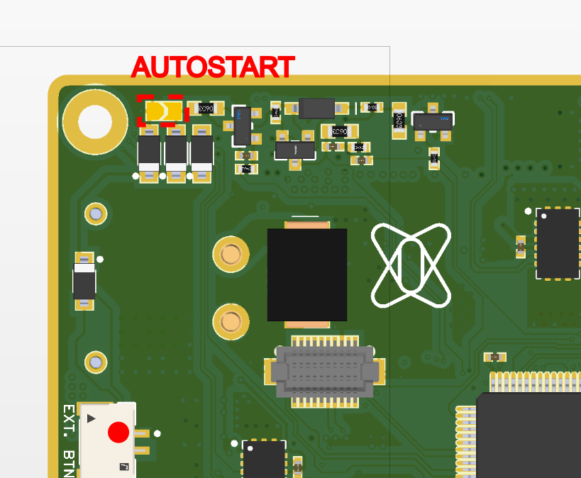
{% hint style="info" %}
Connect the SB to start the board automatically, without the need to press the button
{% endhint %}

<figure><img src="https://341257526-files.gitbook.io/~/files/v0/b/gitbook-x-prod.appspot.com/o/spaces%2FkuuT7PXOBpck5wDlb6XM%2Fuploads%2Fgit-blob-89d7676cfb5910033dc0f5754ecff236ebf93881%2FDCS2.Default_expansion_AUTOSTART_SB.png?alt=media" alt="" width="563"><figcaption><p>Location of AUTOSTART solder bridge</p></figcaption></figure>

| pin | function |
| --- | -------- |
| 1   | GND      |
| 2   | BUTTON   |

</details>


---

# Agent Instructions: Querying This Documentation

If you need additional information that is not directly available in this page, you can query the documentation dynamically by asking a question.

Perform an HTTP GET request on the current page URL with the `ask` query parameter:

```
GET https://test-airvolute.gitbook.io/test-airvolute-docs/autopilots/dronecore-2/boards/adapter-extension-boards/default-expansion-board.md?ask=<question>
```

The question should be specific, self-contained, and written in natural language.
The response will contain a direct answer to the question and relevant excerpts and sources from the documentation.

Use this mechanism when the answer is not explicitly present in the current page, you need clarification or additional context, or you want to retrieve related documentation sections.